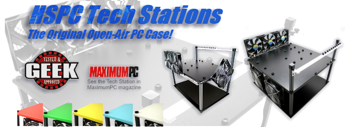
Recent News

On Sale!

Support Center

UPS Tracking

How-To Guides

Bargain Bin

Monthly Giveaway

Testimonials


HighSpeed PC, LLC specializes in unique computer hardware and information for
 cooling, overclocking and accessorizing your PC since 1999.

You will experience exceptional personal service.  
But don't take our word for it, check out our
Testimonials!


Innovatek Tank-O-Matic  Installation Guide

Guide Prepared by Jason David Jacobs, Instructional System Designer

Type: Water Cooling Reservoir
Installation Time: 1 Hour

Index

1. Overview
2. Kit Parts and Explanation
3. Assembly and Case Installation


1. Overview

The assumption in this guide is named that the user has purchased a water cooling system and have this system installed.  This reservoir will work with any water cooling system and best with the Innovatek system for which it is compatible and made to compliment.   

Warning:  The Innovatek system is very high quality and easy to install, however, caution must be used whenever you are working with liquids around electrical components.  For this reason it is highly suggested that you use always have your system unplugged when working on it and use DISTILLED WATER for you installation purposes. Distilled water is available at any grocery store and is a very poor conductor of electricity.  

Before attempting work upon your computer you should always have the power cable unplugged and the system removed to a clean, open spot in which to work.  Several small containers to hold parts and screws will also be helpful but not required. Some tools are required for assembly.


2. Kit Parts and Explanation

The Tank-O-Matic should arrive with all of the following:


   Kit Contents:  

(1) Tank-O-Matic acrylic tube
(2) Aluminum End Caps
(2) Black Restraints
(2) Steel Compression fittings (Screwed into an end cap)

Part Bag containing:
(2) Thin acrylic tubes (one long and one short)
(2) Hex screws with mounting hardware
(2) Self adhesive cushioning


3. Assembly and Case Installation

Tools Needed:

Small adjustable crescent wrench
Flat Head Screw Driver
Phillips Head Screw driver
Knife or Tube cutter
12 Inch Ruler
Dry Erase Pen
Drill
5/32 Drill bit
13/32 Drill bit
Teflon Tape (optional)

To Begin:

Open the Packaging that your reservoir arrived in and remove the Tank-O-Matic help in bubble wrap. Take the bottom end cap off by twisting it counter clockwise while holding the acrylic tube firmly. Once removed place the large reservoir tube safely aside and place the aluminum end cap with compression fittings facing away from you upon your work surface.

WARNING: Do not use a vice or similar restraint to hold the acrylic tube.  The tube is strong and resistant to scratches but will easily scratch or crack due to metal holding device.

Next open the included parts bag and remove the two different length acrylic tubes inside. Both tubes are the same thickness while one is shorter than the other. You will be placing these tubes into their holders in the bottom end of the aluminum end cap.   

Image 3.JPG (143937 bytes)  

 Step 1.   

Place the smaller tube gently into the right hole in the top of the end cap by twisting it into place slowly.  Do not pull or push to hard on the tube or cracking could result.  Once you feel the tube hit the bottom the tube is the fully inserted. It should look like the figure below. 

Image 7.JPG (152224 bytes)

 Step 2.  

Take the longer tube and repeat the process with the hole on the left. Once again take care not to pull or push on the tube to hard to avoid cracking or breaking the tube. Once finished it should look like the figure below if the compression fittings are turned to face you.


   Step 3.  

Place the bottom end cap assembly aside in a safe location and take out the black restraints and mounting hardware. For this step you will need a 12 inch ruler and knife.  Open each of the black plastic restraints to a fully open position as shown below.  Take the strip of cushioning included in the parts bag and cut (2) two inch lengths of strip.  These strips will be placed into the open arm of each restraint as shown below. Make sure to allow room before and after each end of the arm to allow the arm to fully close without cushion getting into either the joint or the clasping end.


 Step 4.  

 For this step you will need a 12 inch ruler and dry erase pen or erasable marking tool such as a grease pen.  This next step is purely optional as you are free to mount the Tank-O-Matic in whatever location you wish.  The setup in this guide was used for ease of use and overall efficiency.  Case room permitting, the tank can also be set up inside you case.  The only configuration not recommended is a horizontal or upside down position.  A horizontal or upside down  setup will cause leaks, place an additional strain on your pump, or cause the potential for the pump to suck air bubbles which will cause inefficient heat transfer. 

Take the black restraint and line it up on the back of your case for the position in which it will hold the tank.

NOTE: Leave room for the Side panel to be fully removable as shown in the picture below. Otherwise the restraint will cover the overlap of the side panel and prevent removal of the panel. 

When you have the restraint placed on the back of the case for measurement.  Add the thickness of your side panel flap to 1- ½ inches and make a mark with your erasable pen at that total measurement.  Measure the same distance at a lower point and make an additional mark.  These two points should form a straight vertical line.  Connect the points with the pen. Take any connectors from your cards into account when deciding upon the drill points for the mounting holes.  You wouldn’t want your black restraint to interfere with connecting your monitor to the video card or other plugs. 

NOTE: Before drilling the mounting holes into the case, all peripheral cards should be removed from their slots.  This is not mandatory, but it helps prevent possible damage to the cards from metal flakes and accidents.

When you have decided upon the mounting locations, make a dot or x across the line you have drawn and use a 5/32 drill bit to drill a hole into the case.  You will be drilling two holes in a straight vertical line and they will end up looking like the figures below. 

 Image 13.JPG (163113 bytes)  Image 14.JPG (155251 bytes)
Image 15.JPG (164514 bytes)


 Step 5.  

Take the mounting hardware from your cup or holder and place the Alan head screw into the included washer and place the assembly into the black restraint as shown below. 

Image 16.JPG (158300 bytes)
   

This step will be repeated upon the second restraint so that both are identical to the figure above.  Place the restraints so that the Alan head screw goes into the holes you have drilled and so that the latches both open to the same side. For later convenience you should arrange them so that the latches open to the left as shown below.  Screw the bottom end cap into its threaded end on the bottom of the tank tube. 

Image 18.JPG (139060 bytes)  Image 17.JPG (164526 bytes)
 

Once both restraints have been placed into position, slide the acrylic tank tube with top and bottom end cap into the top restraint. The tube will not fit into the restraints by placing into the restraints from the side; it must be fed from the top down into the holders. 

Once the Tank-O-Matic is fully inserted into the holders twist the tube in position so that the compression fittings for the water tubes are facing the case.  Mark the center of each compression fitting on the case wall using your erasable pen.  These marking will be used to drill holes through which the water tubes will lead into the tank.  

Once the markings have been made, remove the tank assembly by sliding the tank out through each of the restraints to the top. Once the tank assembly has been removed, unscrew the end cap from the bottom and place it next to the tank.


Step 6. 

Drilling the water tubing holes into the case will be done using a 13/32 drill bit.  If you want an easier hole to work with or a larger area, use a larger sized drill bit.       

NOTE: Before drilling any holes into the case, note the location of expansion cards and objects inside the case and attached to the case wall into which you will drill. Alter the position of your drill point to accommodate any fittings or objects.

Once you have marked your drill points proceed to drill both holes.  


Step 7. 

NOTE: This step assumes that your internal water cooling system has been installed, drained, and prepared to accept the new Tank-O-Matic.  This includes the installation of any fittings needed to route the water tubing to flow to the new position of the Tank-O-Matic.

Take the bottom end cap and remove the top of the compression fitting from both fittings leaving the bottom half of the compression fittings screwed into the end cap.  Then using a crescent wrench, tighten the fitting in the end cap to its fully tightened position. (This guide assumes that some fittings may not arrive fully tightened down.)  Once fully tightened place the bottom end cap without the compression fittings on under the bottom black restraint. Then feed the bottom of the acrylic tank tube into the top restraint and downward. Stop the tube halfway to the bottom restraint.  

Feed the tubing for the water output into the left hole and the tubing for the return water through the right hole, as looking from the rear of the case. Once they have passed through the back of the case, place the top of the compression fitting onto the ends of the tubing in such a manner that the threads face the compression fittings located in the bottom end cap.  

Image 20.JPG (160730 bytes)

Next place the tubing onto the compression fitting ends and over the barb.  Make certain the tubing is all the way back onto the barbed end.  Place the threaded top onto the compression fitting and tighten it down as far as it you can by hand. At any point during the tightening process you can switch to a crescent wrench for final tightening.  You should end up with tubing and ends looking like the figure below. 

Image 22.JPG (187012 bytes)

NOTE: Some users may experience difficulties where the tubing twists while tightening. If this happens to you, simply assemble the tubing and fittings detached from the inside attachments as above and feed the finished product (Above Figure) into the holes you predrilled.

Once the tubing is secured by fully tightening the compression fittings, attach the tubing to your connections inside the case for input and return water lines. 

NOTE: The input (HOT) water line attaches to the long stem acrylic tube, and the return water (from Tank to Radiator or pump) is attached to the short Acrylic tube.  A reverse arrangement can lead to the potential for air in your water tubes.


Step 8.

Take the bottom end cap, now fully assembled and place it just under the bottom black restraint.  Press the Tank-O-Matic large acrylic tube with top end cap in place down through the bottom black restraint and onto the threads of the bottom end cap with attached compression fittings. Be careful to place the bottom end cap’s acrylic tubes into the covering tube while lowering the Tank-O-Matic into position. Refer to the figures below for method.

Image 21.JPG (187001 bytes) Image 24.JPG (161771 bytes)

Once the bottoms end cap’s tubes are inside the Tank-O-Matic tube, lower the tank onto the bottom end cap. Then twist the top half of the Tank-O-Matic tube to thread it onto the bottom end cap while holding the bottom end cap firmly in place to prevent it from twisting.  Your end result should have a gap between the top tube and the bottom end cap that looks similar to the figure below.

Image 18.JPG (139060 bytes)


Step 9.  

Now you are ready to fill your tank and test your setup. 

NOTE: Before adding water, check and re-check your water fittings for gaps or potential leaks.  Make certain that you are using pure distilled water and that any fittings you may have loosened to add the new Tank-O-Matic have been re-tightened.

Option:        If you are using the complete Innovatek system you will fill the black or clear reservoir attached to your Eheim pump first, before filling the Tank-O-Matic. Filling the black or clear reservoir first helps to prime the pump and draw water from the tank.  If you are using no other reservoir before the pump, you may skip this step and proceed to fill the Tank-O-Matic.

To add water to the system, simply remove the top of the Tank-O-Matic by unscrewing the top end cap and adding your distilled water.  Fill the tank to an inch below the bottom of the threads.  The Tank-O-Matic will automatically draw water to fill the lines of the system to a certain point. Allow the water to fill the lines and then add more water to the Tank-O-Matic if the level has dropped further than one inch below the threads.  See the figure below for an example.

Image 24.JPG (161771 bytes)

 NOTE: Allow the system to sit for 15 to 30 minutes with water resting in the tubes.  At the end of 30 minutes check all of your fittings by hand for moisture or leaks.  Fix any leaks prior to system activation.

 
 Step 10. 

Once you have checked for leaks and assembled and filled the Tank-O-Matic with distilled water, you are ready to turn on the system. 

Push the power button for your system or turn on your pump, if you do not have it wired to activate when you power your system.  Watch the Tank-O-Matic drain slightly to completely fill your water lines.  You will notice bubbles coming out of the tubes and filling the top of the Tank-O-Matic, this is due to the system purging itself of air.


NOTE: Due to extensive or longer water lines in your particular system the drain of fluid from the Tank-O-Matic at startup may be more than usual causing the level to drop below the top of the output tube. If this occurs, you must power down the pump and system, fill the tank to one inch below the top threads, place the cap back on, and restart the pump or system.  You do not want the lower return tube to suction any air bubbles which will occur if the water level drops too low.

Once your system is filled and the water lines have purged of air, the system will maintain a bubble free status due to the engineering of the Tank-O-Matic.


Re-use of text and/or graphics from this publication in whole or in part without written permission from a member of HighSpeed PC, LLC is a violation of copyright law.


Copyright © 1999-2008 HighSpeedPC, LLC All Rights Reserved.