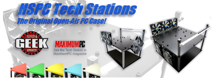
What you will need:
4 Twist Ties, or Lengths of tape
about 1 inch long
1 Small flat head screw driver
1 Package containing 4 Black LED bezels
1 Faceplate
1 Bay Bus
Disconnect the power supply cord in
the back of the computer and make sure the power is off before any
work on the inside of the computer begins.
Once the wires have been spliced to
a length at which they can reach the bay where the Bay Bus will be
placed, either by soldering or using the electrical caps, work can
begin. Make sure there is enough wire length not only to reach the
Bay Bus but also for 4-5 inches to spare coming out the bay. Feed
all of the eight wires in pairs through the 5 ¼ inch bay opening.
Tie the pairs off from each fan or tape them in pairs off about 2
inches from the ends of the wires. This will avoid confusion when
wiring the Bay Bus so that a short does not occur. Once each of
the four pairs of wires has been tied off so that they are easily
identifiable according to fan and Positive and Negative (Red and
Black), you may turn to the task of wiring the Bay Bus.
Take a set of wires at a time and
loop the ends as shown in the pictures below:
Match the red wire with the
positive or red label and the black wire with the negative or
black label as shown below:
Using this process place the looped
ends of the wire into the opening under the screws as shown below
and tighten the screw firmly down into place using the flat head
screwdriver.
Once all of the fans have been wired to the Bay Bus re-check the
wires to make certain that each fan is correctly wired. The colors
of the wires should alternate with no two identical colors being
side by side. This is important as if the Bay Bus is incorrectly
wired it will not work correctly and the potential for shock or
short is present.
Once you have determined that the
wiring is correct you will need to locate a free Molex connector
from the power supply, any free Molex connector from the power
supply will suit this purpose. The connector must be identical to
the one shown below.
This connector is the type that
plugs into the socket on the Bay Bus shown below. The connector
only fits one way and the connection may be tight so you may have
to use a little pressure to make certain that the plug is fully
seated in the socket in the Bay Bus. Ask for adult help if it
becomes to difficult to plug in. HighSpeed PC includes an Y type
splitter to help in this process, which plugs in easily and allows
you to still maintain the same number of connectors available.

Take the faceplate with the holes drilled out and lay it face-up
upon a table. Line the Bay Bus up so that you know exactly which
holes are for the LED's and which are for the switches. Once the
holes are identified push one of the bezels into each of the holes
for the LED.
Place the faceplate down for a
moment. Pick the Bay Bus up and remove the top nut from each of
the switches. Screw the bottom nut half way up the switch length
and leave it at this height, the rest of the hardware above it
should rise as you raise the bottom nut. Save the removed nuts in
one location so that it may be placed back on the top later.
Take the Bay Bus and place it face up, then take faceplate with
the template removed and lay it down upon the Bay Bus. Make
certain the holes line up and re-arrange the faceplate if they do
not. Next line up the Bay Bus behind the faceplate and push the
assembly up to feed the switches and LED's through.
The LED's will be held into place
by the bezels. If you find that you have lined the holes up
incorrectly and the bezels are holding the LED's into place, they
can be removed by lifting one of the black tabs on each of the
bezels on the rear of the faceplate located on top of each LED.
Powering ON:
Once the faceplate is correctly
matched with the Bay Bus, place a single nut on top of each switch
and tighten it down till it will screw in no further. These nuts
will hold the Bay Bus perfectly in place. Place the entire Bay Bus
and faceplate back into the bay, inserting the wires in first.
Replace the face of the computer and re-attach the power cord.
Power on the computer.
The switches will now independently control up to the four
possible fans at either Low, High, or off positions. These
settings are indicated by the light color as mentioned earlier.
Check to see their function and should one or multiple fail to
work properly re-examine this installation guide to check for
missed steps. Should they work fine at high setting and not at
low, then the low settings can be adjusted by using the
potentiometers located shown below.
The potentiometers control the fans
by adding or removing current. Twist them clockwise to increase
current and speed up the fans or counter-clockwise to reduce fan
speed. As with anything concerning electricity inside the case, do
not adjust the potentiometers with the power on. A small Phillips
head screwdriver and a half turn clockwise should be all that's
needed to raise the current enough to power larger fans from the
stock settings.
Enjoy your new Bay Bus.
Re-use
of text and/or graphics from this publication in whole or in part
without written permission from a member of HighSpeed PC, LLC is a
violation of copyright law.