|
 |
 |
|
ATX Power BracketMotherboard Power Control without the Case...on a PCI bracket!
ATX Power Switch:
System power (on/off/standby) controlled by momentary switch attached to the
motherboard’s 2 pin power switch header.
Reset Switch: Reboots PC without powering system off, attached to the motherboard's 2 pin reset switch header.
(either switch in this kit can be used)
System Power LED
(green):
Lights when power is ON.
Blinks when system is in standby or sleep. Now with
separate +/- pin connectors for either 2 pin or 3 pin motherboard connections.
Hard Drive Activity LED (red):
2 pin connector. Blinks with hard
drive activity.
Notes:
-
See
More Details for how to change the Power LED's 3 pin/2pin connectors (earlier model Power Brackets)
-
See your motherboard manual for pin
locations and panel functions.
-
If LED's or switches won't function, or the HDD LED remains on
continuously, just pull them off the motherboard header and reverse
installation.
-
See
also our
ATX Control Kit - Its included with all Tech Stations
-
System
Alert Speaker not included with the bracket
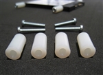
Changing the 3 pin Power LED connector to the 2 pin connectorWe do include a spare 2 pin connector with the kit for boards that
won't allow for 3 pin LED connections. Here's how to change out
the connectors...
To remove the 3 pin connector: - Look very closely on the 3 pin connector attached to the Power
LED, on the side opposite the "Power LED" lettering notice two
important details:
- First, there is a small triangle imprinted on the
connector
above the green wire (there's also one of these triangles on the
2 pin connector), this labels which slot the green wire belongs in.
- Second, you will see small openings in the housing where you can
see the internal metal wire connectors. Just below these small
openings are plastic tabs that can be gently pried outward with a
fingernail, a pin, or a very small flat-head screwdriver.
- While pulling gently on the wire, pry the plastic tab outward just enough to release the
inner metal connector. The green wire/connector
should come right out.
- Do this for both wires.
To install the new 2 pin connector: - Remember there is a
small triangle imprinted on the connector that indicates the slot
for the green wire. Make sure the green wire goes in the correct
slot.
- Push the metal pins all the way in (doing both at the same time is best), making sure the
plastic tabs get seated to hold them in place and you're ready to
go.
If you have any questions we're here to help!
|
|
|
 |
|
 |
|
|
|
 |
|
 |
|
Features
The
ATX Power Bracket includes:
-
2
Push Button Switches – Power on/off and Reset
-
1 Green LED – Power indicator (New! Separate +/- connectors)
-
1 Red LED – Hard Drive activity
-
1
Add-in card bracket
-
Cable
length: 20" (51cm)
-
Connectors
are labeled
-
The
bracket comes fully assembled and ready to use
-
1 year replacement warranty
Also
great for isolating problem case switches!
|
|
|
|
|
|
|
|
|